
Your Design vs. The Machine: A Practical Guide to How Injection Molding Works
By Ichiplas Process Engineering Team · Oct 2025 · Updated Nov 2026 · Reviewed by the Ichiplas engineering team
As a product designer or engineer, you live in the world of CAD models and design intent. But to bring that vision to life, it has to meet the physical realities of the machine that will produce it.
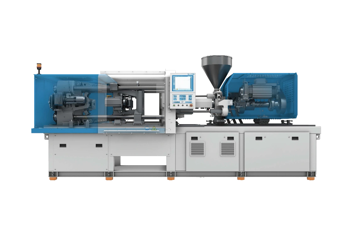
The gap between your 3D file and a million perfect parts is bridged by the injection molding machine. Understanding its core functions isn't just academic; it directly impacts your part design, tooling costs, and the quality of your final product. So let's break down the two main systems you need to be aware of: the injection unit and the clamping unit.
The Injection Unit: From Pellet to Part
The injection unit's job is straightforward: melt raw plastic and force it into your mold with extreme precision. It's a process of heat, pressure, and tight control.
Here's the breakdown:
1. Material Feed:
The process starts with raw plastic pellets, which are loaded into a hopper. This funnel feeds the pellets into the main barrel of the machine.
2. Melt and Convey:
Inside the barrel, a heavy-duty reciprocating screw does two things at once: it rotates to push the pellets forward while heater bands surrounding the barrel melt them into a consistent, liquid state.
3. High-Pressure Injection:
Once the right volume of molten plastic (the “shot”) has accumulated at the front of the barrel, the screw stops rotating and acts like a hydraulic ram. It pushes forward, injecting the plastic through the nozzle and into your mold cavity at pressures that can easily exceed 15,000 PSI.
The key takeaway here is control. Our operators set precise temperatures, pressures, and shot sizes for every tool. This is how we ensure every part is identical, from the first off the line to the last.
The Clamping Unit: Holding the Line Under Pressure
If the injection unit is about force, the clamping unit is about containment. When you inject molten plastic at high pressure, that same pressure tries to force the two halves of the mold apart. If it succeeds, you get flash—a thin, unwanted sheet of plastic around your part's edge. It's a classic sign of a process issue.
The clamping unit is a massive hydraulic or all-electric press that prevents this. It has two primary functions:
1. Counteracting Injection Force:
The clamping unit holds the mold shut with immense force, measured in tonnage. A 200-ton press, for example, applies 200 tons of force to keep the mold perfectly sealed during injection. This force must always be greater than the separation force generated by the plastic pressure inside the mold.
2. Ensuring Precise Alignment:
A mold can weigh several tons. The clamping unit's platens ensure the two halves of the tool—the A-side and B-side—are perfectly aligned every single time. Without this precision, parts would be inconsistent, and the tool itself could be damaged.
This is why production tools are made from hardened steel. No other material can withstand these repeated, high-pressure cycles without deforming.
Why This Matters for Your Design
The entire process is a rapid, repeatable cycle: the clamp closes, the plastic injects, the part cools under pressure, the clamp opens, and the part is ejected. This cycle can be as short as a few seconds.
Understanding this interplay between injection and clamping is fundamental to good part design. The forces at play are the reason we talk so much about design for manufacturability (DFM). They are the reason draft angles are non-negotiable for clean part ejection and why maintaining uniform wall thickness is the best way to prevent cosmetic defects like sink marks.
Where the Cycle Time Goes
A molding cycle has five stages. Cooling dominates, which is why wall thickness has more effect on unit cost than almost any other design decision.
| Stage | What happens | Typical share of cycle |
|---|---|---|
| Clamp | Mold closes and clamp force builds | About 5% |
| Injection (fill) | Screw pushes melt into the cavity | About 5 – 10% |
| Pack and hold | Extra material is packed in to offset shrinkage | About 10 – 20% |
| Cooling | Part solidifies while the screw prepares the next shot | About 50 – 70% |
| Open and eject | Mold opens and the part is ejected | About 5 – 10% |
Estimating Clamp Tonnage
A quick estimate: clamp force ≈ projected area of the part (and runner) facing the opening direction × a material factor. A 100 cm² ABS part needs roughly 100 × 0.4 ≈ 40 tonnes, before a safety margin.
| Material | Tonnes per cm² | Tons per in² |
|---|---|---|
| PP, PE | 0.3 – 0.5 | 2 – 3 |
| ABS, PS, PC/ABS | 0.3 – 0.6 | 2 – 4 |
| POM, PBT | 0.5 – 0.7 | 3 – 4.5 |
| PC, nylon, glass-filled grades | 0.5 – 0.8 | 3 – 5 |
Thin walls and long flow lengths push the factor up. Add a 10–20% margin, and confirm with mold flow analysis for large parts. Ichiplas runs presses from 50 to 360 tonnes.
Frequently Asked Questions
How long is a typical injection molding cycle?
Most small to medium parts run on cycles of roughly 10 to 60 seconds. Thin-walled packaging can cycle in a few seconds, while large, thick parts can take a minute or more. Cooling is usually 50–70% of the cycle, so wall thickness is the biggest driver.
How much clamp force does my part need?
Estimate it by multiplying the part's projected area (the area facing the mold opening direction, including runners) by a material factor of roughly 0.3 to 0.8 tonnes per square centimetre (2 to 5 tons per square inch), then add a 10–20% safety margin. Thin walls and long flow paths need the higher end of the range.
What causes flash on injection molded parts?
Flash happens when molten plastic escapes between the mold halves or around moving components. Common causes are insufficient clamp force for the part's projected area, excessive injection or pack pressure, worn or damaged parting line surfaces, and melt that is too hot or too fluid.
What is the difference between hydraulic and electric injection molding machines?
Hydraulic machines use hydraulic cylinders to drive the screw and clamp and are robust and cost-effective at high tonnages. All-electric machines use servo motors, offering better repeatability, lower energy use and cleaner operation. Hybrid machines combine both. Part quality depends more on mold design and process control than on the drive type.
Why does wall thickness affect the cost of a molded part?
Cooling time rises roughly with the square of wall thickness, and cooling is the longest stage of the cycle. A thicker wall therefore means a longer cycle, fewer parts per hour and a higher unit price, as well as more material and a greater risk of sink and warpage.
What's Next?
We've covered the machine — see our plastic injection molding services to learn how we apply this in production. Now it's time to look at the custom tool at its heart. In our next article, we'll follow the path of the plastic inside the mold itself in The Journey of Plastic: Understanding Sprues, Runners, and Gates.
Getting your design ready for production can feel complex. Our team in Johor Bahru lives and breathes this process every day. If you want to ensure your design is optimized for manufacturing from the start, reach out to us. We're here to help.
Get Free Quote
Contact us today to learn more about our services and how we can help you with your next project.