
What is Draft Angle and Why is it Critical for Your Part?
By Ichiplas Design Engineering Team · Oct 2025 · Updated Nov 2026 · Reviewed by the Ichiplas engineering team
If you take only one design rule away from this series, make it this one: you must apply a draft angle to your parts.
It's a non-negotiable principle of injection molding, and overlooking it is one of the most common—and entirely avoidable—mistakes we see from new designers.
So, what is it? A draft angle, or “draft,” is simply a small taper applied to the vertical walls of your part, parallel to the direction the mold opens. Instead of being perfectly 90 degrees to the parting line, the walls are angled slightly. It might seem like a minor detail, but it's the difference between a part that ejects cleanly and a part that gets ruined.
Why a Perfectly Vertical Wall Fails
Imagine trying to pull a perfectly straight-walled cup out of a block of hardened clay. As you pull, the entire surface of the cup scrapes against the clay, creating immense friction. You might also create a vacuum at the bottom, making it even harder to remove.
The same thing happens inside a steel mold. When your part cools, it shrinks and grips tightly onto the mold's core. Ejecting a part with vertical walls (zero draft) causes two major problems:
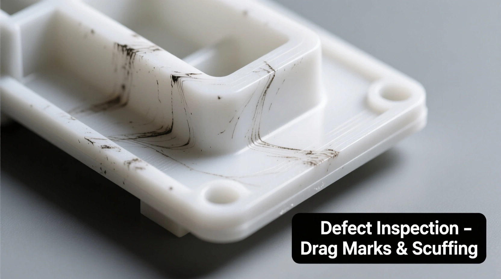
1. Drag Marks:
The ejector pins push the part out, but its surfaces scrape along the highly polished steel mold. This can cause long, ugly scratches or scuff marks on your part's finish.
2. Breakage:
The high friction and potential vacuum can mean the ejection force required is greater than the strength of the plastic. The result is that the ejector pins simply punch holes through the part, leaving it stuck in the mold and causing costly downtime.
Draft: The Simple, Elegant Solution
Adding a slight taper solves both problems instantly. Even with just one degree of draft, the moment the part begins to move, its walls separate from the mold surface. This breaks the vacuum and eliminates nearly all friction. The part slides out smoothly and cleanly, cycle after cycle.
As a general rule of thumb:
- Aim for a minimum of 1 to 2 degrees of draft on all walls.
- For textured surfaces (like a matte or pebbled finish), you need more draft—typically an extra 1 degree per 0.001 inch of texture depth. This is to prevent the texture from being scraped off during ejection.
How Much Draft Do You Need?
Use this as a starting point when applying draft in CAD. More is always easier to mold; less is possible but costs you in ejection risk and polishing.
| Surface or feature | Recommended draft | Why |
|---|---|---|
| Polished surfaces (SPI A / B) | 0.5° – 1° | Low friction, but still needs some taper |
| Standard / unspecified surfaces | 1° – 2° | Reliable default for most walls |
| Light texture (e.g. matte, SPI C / D) | 1.5° – 3° | Texture grips the steel during ejection |
| Textured (rule of thumb) | +1° per 0.025 mm (0.001 in) of texture depth | Prevents the texture from being scuffed off |
| Heavy leather or grain texture | 3° – 5°+ | Check the texture supplier's minimum |
| Tall walls and deep cores (> 50 mm) | Add 0.5° – 1° | Shrinkage onto the core increases with depth |
| Ribs | 0.5° – 1° per side | Keeps the rib tip from thinning too much |
| Shut-offs and pass-through cores | 3° minimum | Protects sliding steel faces from galling |
Inside walls (core side) matter most because the part shrinks onto the core. Always confirm texture-specific draft with the texture specification you choose (e.g. VDI 3400 or a Mold-Tech pattern).
Frequently Asked Questions
What is a good draft angle for injection molding?
A draft of 1 to 2 degrees on all walls parallel to the mold opening direction is a good default. Polished surfaces can work with 0.5 to 1 degree, while textured surfaces need more — typically an extra 1 degree for every 0.025 mm (0.001 in) of texture depth.
Do I need draft on both the inside and the outside of a part?
Yes. Every face parallel to the direction of pull needs draft, on both the cavity (outside) and core (inside) sides. The core side is the most critical, because plastic shrinks onto the core as it cools and grips it during ejection.
Can an injection molded part have zero draft?
Sometimes, on short features with a high polish and careful ejection, or by forming the zero-draft face with a side-action that moves away before ejection. Both options add tooling cost and risk drag marks, so zero draft should be reserved for faces where it is functionally essential.
How does draft affect part dimensions?
Draft makes a wall slightly thicker at its base than at its tip, and changes inside and outside dimensions along the wall's height. On your drawing, state where a critical dimension applies — at the top, bottom or mid-height of the drafted face — so the toolmaker and inspector measure the same thing.
Why are there scratches or drag marks on my molded part?
Drag marks are almost always caused by insufficient draft for the surface finish, often on textured faces or on the core side where shrinkage grips the steel. Increasing draft, polishing in the direction of ejection, or adjusting cooling so the part shrinks less onto the core usually solves it.
What's Next?
Draft ensures your part can leave the mold. But what ensures it looks good when it does? In our next article, we cover the golden rule for preventing cosmetic defects: The Golden Rule: Why Uniform Wall Thickness is Key to Quality Parts.
Getting your design ready for production can feel complex. Our team in Johor Bahru lives and breathes this process every day. If you want to ensure your design is optimized for manufacturing from the start, reach out to us. We're here to help.
Get Free Quote
Contact us today to learn more about our services and how we can help you with your next project.