
How to Design Functional Features: Ribs and Bosses
By Ichiplas Design Engineering Team · Oct 2025 · Updated Nov 2026 · Reviewed by the Ichiplas engineering team
You've followed the golden rule and designed your part with a thin, uniform wall thickness. The result is a part that's free from sink marks and warping, but it might feel flimsy.
So how do you add strength and rigidity without creating thick sections that violate the rule?
The answer lies in two of the most common functional features in plastic design: ribs and bosses. These are the internal skeleton of your product, providing structural support and mounting points without compromising the cosmetic exterior.
Strengthening with Ribs
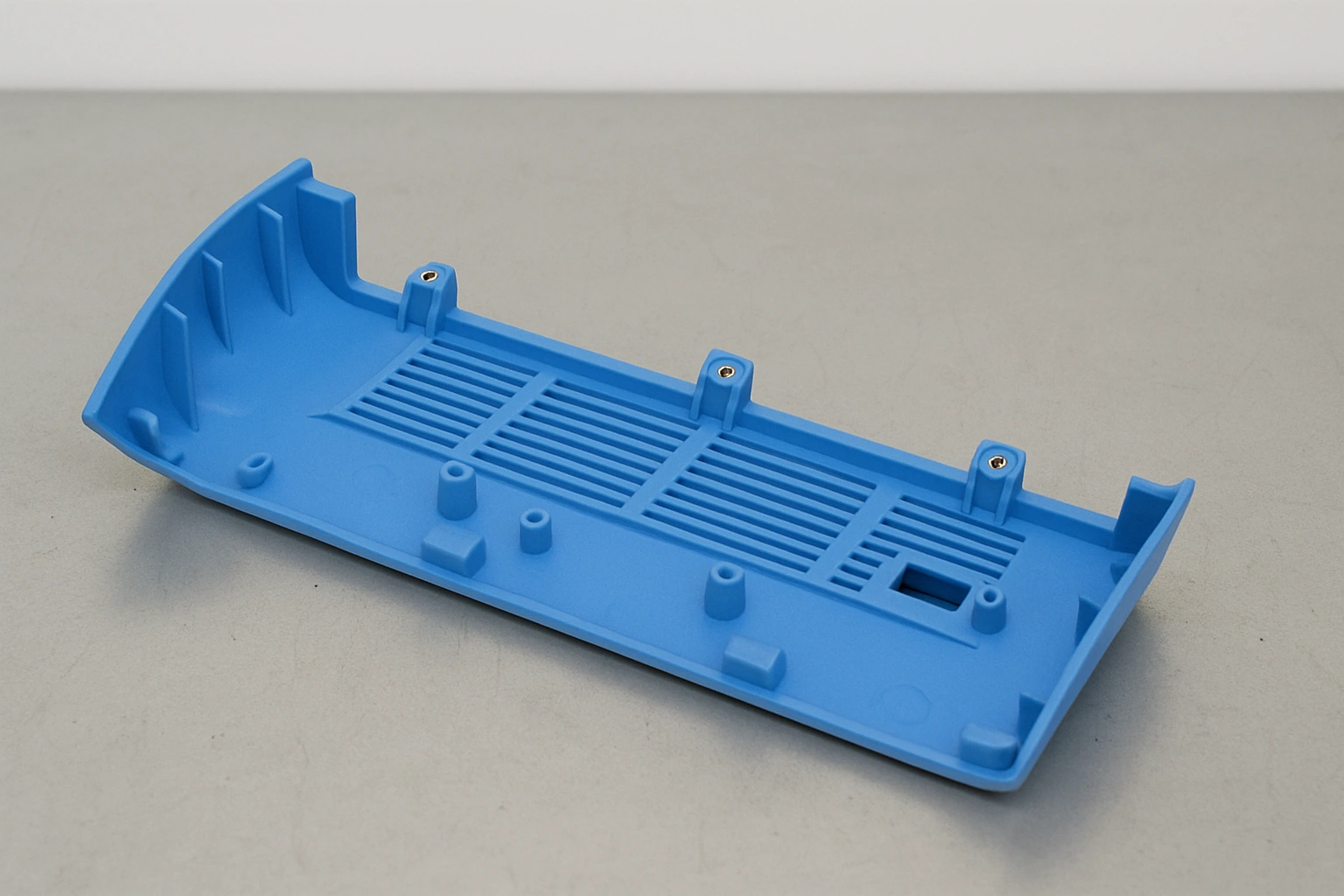
Ribs are thin, wall-like features designed to add stiffness and support to a part. A well-designed grid of ribs can make a 2mm thick part feel as rigid as a 4mm solid slab, but with a fraction of the material and cooling time.
The single most important rule for designing ribs is: A rib's thickness should be approximately 40% to 60% of the nominal wall thickness of the part.
Why? If a rib is too thick at its base, it creates a mass of plastic that will cool slowly and cause a sink mark on the cosmetic surface directly opposite it. By keeping the ribs thin, you add the structure you need without creating a cosmetic problem.
Creating Mount Points with Bosses
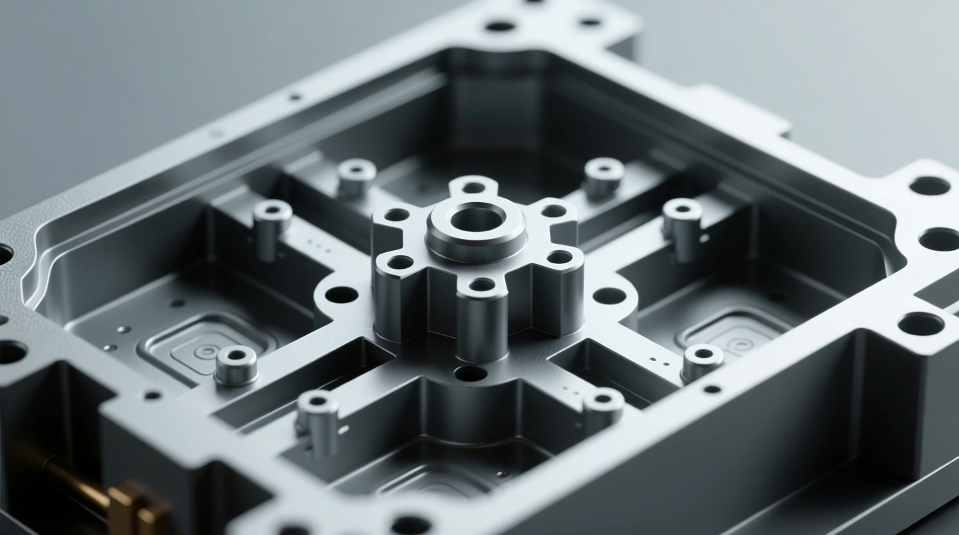
A boss is typically a cylindrical feature designed to receive a screw, a threaded insert, or an alignment pin. They are the go-to feature for assembling your product.
The same rules for ribs apply to bosses: they are essentially thick walls, so they must be designed to avoid sink.
- Core them out: Never design a solid boss. It should be hollowed out to maintain a wall thickness consistent with the rest of your part.
- Use Gussets: Freestanding bosses can be weak and get knocked over by the flow of plastic. It's best practice to connect them to nearby walls with thin support ribs, often called gussets, for stability.
By correctly designing ribs and bosses, you create a part that is both lightweight and strong — the hallmark of an efficient and well-engineered plastic product. Our mold design team can help you optimize these features for manufacturability.
Rib and Boss Design Rules at a Glance
Express each rule as a ratio of the nominal wall thickness (t). For a 2.5 mm wall, a 50% rib is 1.25 mm thick.
| Feature | Rule of thumb | What goes wrong if ignored |
|---|---|---|
| Rib thickness | 40–60% of t (lower end for high-shrink PP, PE, POM, nylon) | Sink marks opposite the rib |
| Rib height | ≤ 3 × t | Short shots, sticking, thin fragile tips |
| Rib spacing | ≥ 2 × t between ribs | Hard-to-cool thin steel, slow cycles |
| Rib draft | 0.5° – 1° per side | Ribs stick in the mold |
| Rib base fillet | 0.25 – 0.5 × t | Stress concentration, or sink if too large |
| Boss wall thickness | ≤ 60% of t | Sink on the cosmetic face |
| Boss outer diameter | About 2 – 2.5 × the screw or insert diameter | Boss splits when the screw is driven |
| Boss height | Avoid exceeding about 3 × the boss OD; support taller bosses | Bosses bend or fill poorly |
| Gussets | Thickness about 50% of t, height below the boss top | Free-standing bosses get pushed over by flow |
For screw bosses, use the pilot hole diameter your screw supplier recommends for the specific resin. For high-load or frequently serviced joints, consider a threaded brass insert instead.
Frequently Asked Questions
How thick should a rib be on a plastic part?
A rib should be about 40% to 60% of the nominal wall thickness. Use the lower end for high-shrink semi-crystalline materials such as PP, PE, POM and nylon, and up to about 60% for low-shrink amorphous materials such as ABS and PC. Thicker ribs cause sink marks on the opposite face.
How tall can a rib be?
Keep ribs no taller than about three times the nominal wall thickness. If you need more stiffness, use two or more shorter ribs spaced at least two wall thicknesses apart rather than one tall rib, which is hard to fill, vent and eject.
Why does a screw boss cause a sink mark on the outside of my part?
A solid or thick-walled boss creates a mass of plastic that cools and shrinks after the surrounding wall, pulling the outer surface inward. Core the boss so its wall is no more than about 60% of the nominal wall, and connect it to nearby walls with thin ribs or gussets instead of thickening its base.
How do I size a boss for a self-tapping screw?
Make the boss outer diameter about 2 to 2.5 times the screw's major diameter, and use the pilot hole size the screw manufacturer specifies for your resin. Add a small counterbore or chamfer at the top so the first thread doesn't split the boss, and design enough engagement length for the required pull-out strength.
When should I use a threaded insert instead of a screw boss?
Use a threaded metal insert when the joint will be opened and closed repeatedly, carries a high load, or needs a machine-screw thread. Self-tapping screws into plastic bosses are cheaper but wear the thread after a few cycles. Inserts can be molded in, heat-set or ultrasonically installed after molding.
What's Next?
Now that you can strengthen your part and screw it together, let's look at a more elegant assembly method. Our next article dives into a classic feature: A Guide to Designing Snap-Fits for Injection Molding.
Getting your design ready for production can feel complex. Our team in Johor Bahru lives and breathes this process every day. If you want to ensure your design is optimized for manufacturing from the start, reach out to us. We're here to help.
Get Free Quote
Contact us today to learn more about our services and how we can help you with your next project.